UML Model Components
 UML Model Elements
Use Case = user Interaction with the system
Actor = Any system / user who interacts with the system.
Component = .dll, .exe, COM+, EJB etc
Package = Group of similar Classes / Use cases/ Actors
You can Import / Export any model element for Re-use
UML Views
4 views:
Use Case View
Logical View
Component View
Deployment View
UML Diagrams:
UML has 7 Diagrams to illustrate different aspects of the system:
Use Case Diagram
Sequential Diagram
Collaboration Diagram
Class Diagram
State Transition Diagram
Component Diagram
Deployment Diagram
Each diagram has a purpose and an intended audience.
Use Case Diagram
 Use Case Diagram shows interactions between use cases and Actors.
Use Case Diagram represent the Requirements of the system from the user’s perspectives.
Intended Audience: Users, Project Manager, Analyst, Tester, Developers, Architect for understanding the system requirements.
Sequence Diagram For Money Withdrawal Use Case

Very important UML diagram from the point of view of requirements elaboration and preparing Test cases.
Sequence diagram shows flow of functionality (Sequence of operations) through a Use Case.
During the process of developing Sequence Diagram you can visualize / analyze normal and abnormal use of the system / use case.
Intended User:
Analyst : Check flow of process
Developers: Check objects that needs to be developed.
Testers : Check to develop Test Cases
Collaboration Diagram
 Collaboration diagrams show exactly he same interactions as the sequence diagram but from a different perspectives.
Architects use this diagram to check distribution of processing between objects.
Class Diagram:
 Class diagrams show interactions between classes (Objects) in the system.
Classes contain information (attributes) and behavior( operations) that act on that information.
Intended User:
Developers : Check to develop classes. Generate skeletal code
Architects :Check the design of the system
If a class contains too many operations, the architect may split the class into multiple classes.
State Transition Diagram
Dynamic states of a bank account.

State Transition diagrams model the various states in which an object can exist.
While class diagrams show a static picture of the classes. State Transition diagrams show more dynamic behavior of a system.
State Transition diagrams are NOT created for every class. They are created for very complex class.
Component Diagram
 Component diagram show a physical view of your model.
Shows relationship between software components like code libraries, .dll, Client.exe, Server.exe etc
Each of the classes in the rose model is mapped to a source code component. Once the component have been created they are added to the component diagram.
Intended user: Build engineer for creating builds.
Deployment Diagram:
 Deployment diagram shows physical layout of the network where the various components will reside.
The physical deployment may differ from the logical architecture of the system. Ex: The system may have 3-tier architecture, but the deployment may be 2-tiered.ie The Client may be deployed in one machine and the Sever component and DB may be deployed in a Server machine.

Use Case = user Interaction with the system
Actor = Any system / user who interacts with the system.
Component = .dll, .exe, COM+, EJB etc
Package = Group of similar Classes / Use cases/ Actors
You can Import / Export any model element for Re-use
UML Views
4 views:
Use Case View
Logical View
Component View
Deployment View
UML Diagrams:
UML has 7 Diagrams to illustrate different aspects of the system:
Use Case Diagram
Sequential Diagram
Collaboration Diagram
Class Diagram
State Transition Diagram
Component Diagram
Deployment Diagram
Each diagram has a purpose and an intended audience.
Use Case Diagram

Use Case Diagram represent the Requirements of the system from the user’s perspectives.
Intended Audience: Users, Project Manager, Analyst, Tester, Developers, Architect for understanding the system requirements.
Sequence Diagram For Money Withdrawal Use Case
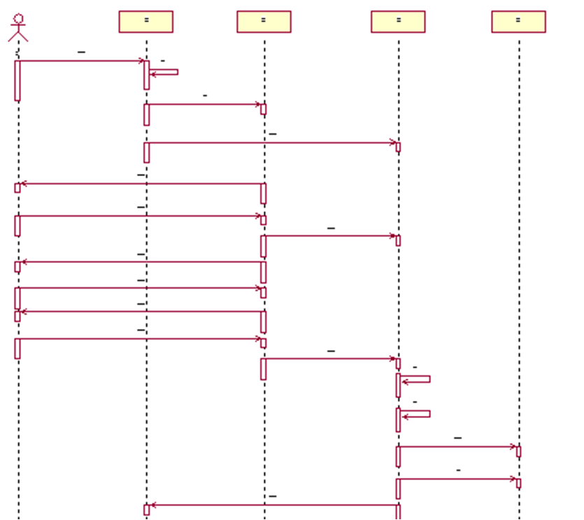
Very important UML diagram from the point of view of requirements elaboration and preparing Test cases.
Sequence diagram shows flow of functionality (Sequence of operations) through a Use Case.
During the process of developing Sequence Diagram you can visualize / analyze normal and abnormal use of the system / use case.
Intended User:
Analyst : Check flow of process
Developers: Check objects that needs to be developed.
Testers : Check to develop Test Cases
Collaboration Diagram

Architects use this diagram to check distribution of processing between objects.
Class Diagram:

Classes contain information (attributes) and behavior( operations) that act on that information.
Intended User:
Developers : Check to develop classes. Generate skeletal code
Architects :Check the design of the system
If a class contains too many operations, the architect may split the class into multiple classes.
State Transition Diagram
Dynamic states of a bank account.
State Transition diagrams model the various states in which an object can exist.
While class diagrams show a static picture of the classes. State Transition diagrams show more dynamic behavior of a system.
State Transition diagrams are NOT created for every class. They are created for very complex class.
Component Diagram

Shows relationship between software components like code libraries, .dll, Client.exe, Server.exe etc
Each of the classes in the rose model is mapped to a source code component. Once the component have been created they are added to the component diagram.
Intended user: Build engineer for creating builds.
Deployment Diagram:

The physical deployment may differ from the logical architecture of the system. Ex: The system may have 3-tier architecture, but the deployment may be 2-tiered.ie The Client may be deployed in one machine and the Sever component and DB may be deployed in a Server machine.
No comments:
Post a Comment